What is a thermistor?

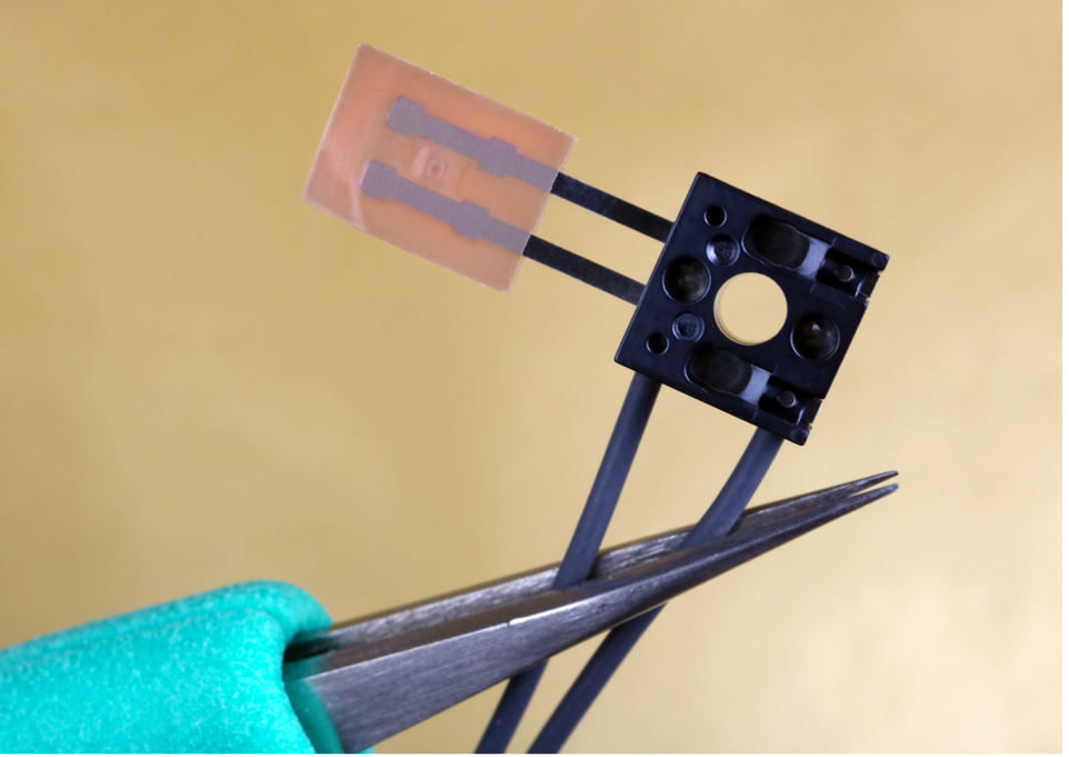
A thermistor is an element that senses temperature and is made up of sintered semiconductor material which displays a big change in resistance in proportion to a small alteration in temperature. They normally have negative temperature coefficients meaning the resistance goes down as the temperature goes up.

Thermistors are constructed using a combination of metals and metal oxide materials. Once they are mixed, the materials are formed and pushed into the required shape. They can then be used naturally as disk-style thermistors without any changes needed. Alternatively, they can be further shaped and put together with lead wires and coatings to create bead-style elements.

How do thermistors compare to RTDs?

Whilst RTDs change resistance in an almost linear way, thermistors have a very non-linear change in resistance and reduce their resistance as temperature increases. They continue to be a popular way of measuring temperature for several reasons including:

  • Their increased resistance change per degree of temperature offers better resolution
  • There is a high level of repeatability and stability
  • Impressive interchangeability
  • Their small size means they can respond faster to changes in temperature

Thermistors typically have two types of coatings: epoxy for use in lower temperatures (-50 to 150C) and glass coatings for higher temperature applications (-50 to 300C). These coatings are used mechanically to protect the bead and wire connections whilst offering a degree of protection from corrosion and/or corrosion too. A very small diameter and solid copper or copper alloy wires are normally supplied with thermistors. In most cases, these wires are tinned to allow for easy soldering.

Base resistance

NTC thermistors decrease in resistance with increased temperatures. This is also the case for how much resistance change per degree it will provide. For quite low temperature applications (-55 to around 70C) lower resistance thermistors are generally used. Higher resistance thermistors are used for higher temperature applications in order to optimise the resistance change per degree at the temperature that is needed. These elements are available in a range of resistances and “curves” and resistances are typically specified at 25C.

How does a thermistor work?

Unlike RTDs and thermocouples, thermistors don’t have standards linked with their resistance versus temperature characteristics or curves. As a result, there are several different ones you can choose from. Each material will offer a different resistance vs temperature “curve”. Certain materials will have better stability whilst others have higher resistances so they can be made into bigger or smaller thermistors.

What thermistor is right for your application?

Whether you are replacing a thermistor or getting one for a completely new application, there are three key things you will need to consider in order to achieve the best result. These are:

  • For new applications, select proper base resistance or correctly specify the base resistance of the one that you are replacing.
  • When specifying resistance-temperature correlation, make sure to be precise. For replacements, have info on existing thermistor ready
  • Packaging style and size
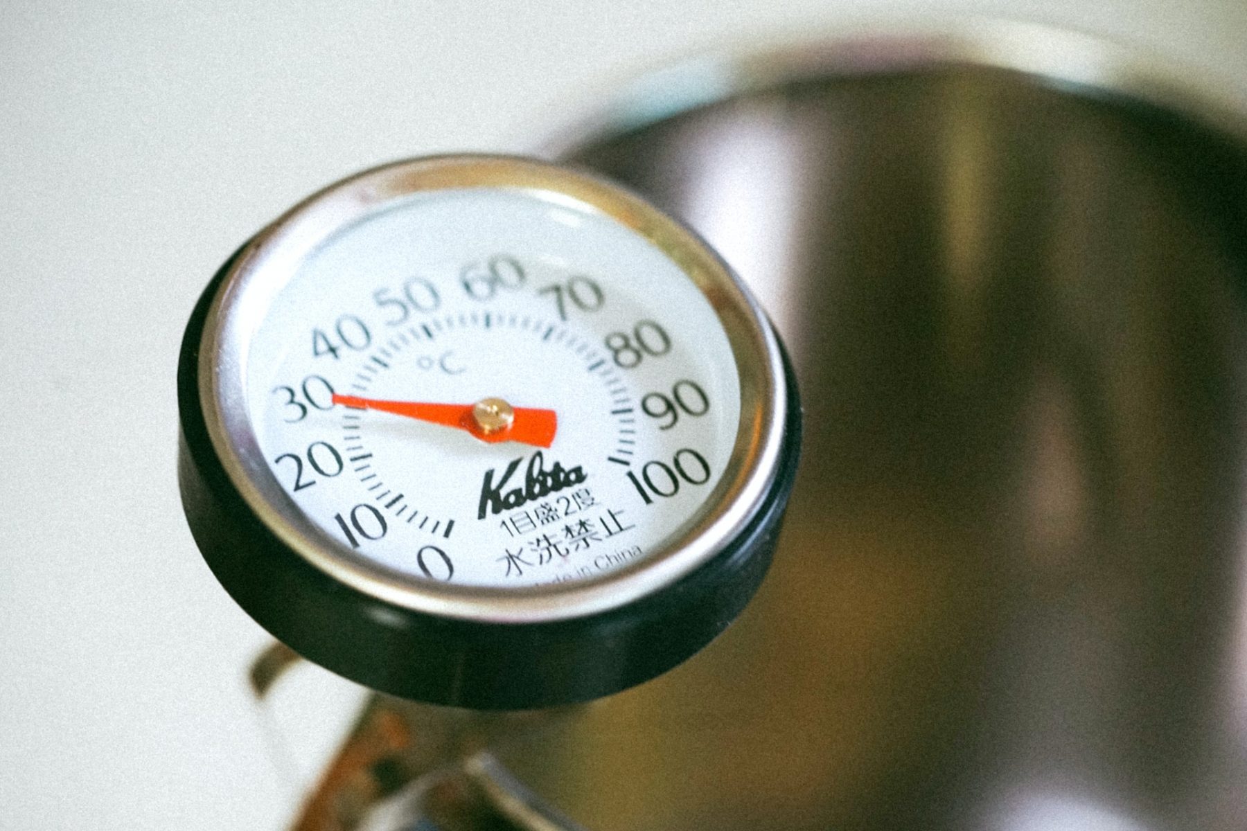
Thermistor accuracy

Thermistors are one of the most precise temperature sensors on the market. However, they can be quite restricted in terms of their temperature range, operating across a range of 0 to 100C. If you don’t think a thermistor will be right for your normal thermocouple applications, stick with your thermocouple. Despite having a number of useful benefits, such as being chemically stable and so not massively susceptible to aging, a thermistor isn’t the right fit for every industry or process because of the limited parameters.

Size or sensor package style

When the user has determined the right resistance and curve, they should consider how they intend to use the thermistor. So, when they are choosing the right size or packaging for the sensor, it’s important to remember that in the same way as any other sensor, a thermistor will only measure its own temperature.

Thermistors cannot be submerged in a process. They are small and quickly react to temperature changes since they are only separated from the environment by a thin epoxy layer. However, you can get different styles of thermistors for different uses.

General purpose

General purpose designs can be work in a broad range of applications. From electronic equipment to structures, processes and design, and reliability testing uses, sensors of this style are easy to fit and monitor over time.

Liquid immersion measurement

Thermistors need to be protected from corrosion when they are exposed to liquids as well be carefully positioned in the fluid so it will arrive at the required temperature. This is normally done using closed ended tubes and housing that are specifically designed for the job. You need to take care and ensure that there is a clear thermal path to the thermistor and that thermal mass is as small as it can be.

How can TRM help?

At TRM, our team provide engineered solutions that perform at the highest temperatures and in the harshest environments. We are specialists in all thing’s temperature measurement, trace heating, and fireproof wiring, offering a range of useful products like MI thermocouple cable to ensure our customers get the solutions they need in their business operations. Contact us today to discuss your specific requirements and what we can do for you.


What is a resistance thermometer?

A resistance thermometer or resistance temperature detector (RTD) is a device which measures temperature through the resistance of a conductor. Resistance of the conductor can vary with time. It is this property of the conductor that is used for industrial temperature measurement. The RTD’s primary purpose is to produce a resistance alteration in response to temperature.

Metals usually exhibit high temperature coefficients, indicating resistance increases as temperature rises. On the other hand, carbon and germanium typically demonstrate low temperature coefficients, thereby showing a resistance decrease with increasing temperature.

The material used in a resistance thermometer

The resistance thermometer has a sensitive element that is made from the purest metals such as platinum, copper, or nickel. There is a direct connection between the resistance of the metal and temperature. In most cases, platinum is used in resistance thermometers due to its high accuracy, stability, and its ability to withstand extremely high temperatures.

Metals like gold and silver are not used for RTD heat trace because they don’t exhibit the high resistance that is needed, they have low resistivity. Whereas a material like tungsten has high resistance but is very brittle. Copper is often used to make the RTD element as it has low resistivity and is a cheaper metal. The only downside to copper is that is has less linearity.

The maximum temperature of the copper is around 120C. An RTD material is made from either platinum, nickel, or nickel alloys. Nickel wires work well within a certain temperature range but are not linear. The RTD sensor requires a conductor with a high resistivity so a small amount of conductor volume can be used. The resistance should vary as much as possible with temperature.

Construction of a resistance thermometer

The resistance thermometer is put inside a protective tube to keep it from becoming damaged. Platinum wire is wound around a ceramic bobbin to form the resistive element, which is placed inside a stainless or copper steel tube. Lead wire is attached to the element and external lead and covered with an insulated tube to protect against short circuits. Ceramic is an insulator for high-temperature elements, while glass or fibre is used for low-temperature.

How a resistance thermometer works

The tip of the resistance thermometer is positioned near the heat source and heat is evenly distributed across the resistive element. Changes in the resistance vary the temperature of the element and the final resistance is measured.

Linear approximation

Linear estimation is predicting the resistance-temperature correlation using a linear equation. Quadratic approximation is a precise guess of the resistance-temperature connection expressed as a quadratic equation.

Quadratic approximation

Quadratic approximation is a precise guess of the resistance-temperature connection expressed as a quadratic equation.

The resistance thermometer is less responsive, and the material used to make the element is cheaper.

How can TRM help?

If your business manufacturing processes need heat management then temperature monitoring and control will be extremely important to you. Our high-temperature cable and measurement sensors can suit practically any environment in any industry.

The team at TRM are experts in heat management and industrial temperature measurement, offering services relating to design, supply, and installation as well as providing a wide selection of temperature-related products. Contact us today to discuss the specific requirements of your operations and find out how we can help you.

What is a J type thermocouple?

A J type thermocouple is one of the most common and applicable thermocouple types. The most important thing to know about this thermocouple is that is has a small temperature range and a reduced lifespan if used at higher temperatures. It has positive leg which is made from an iron wire and negative leg consisting of a constantan (copper 55% and nickel 45%) alloy wire. It is the Curie Point of the iron at 770C that gives type J its restricted temperature parameters of -40C-750C. 

If this thermocouple is used in an oxidising environment at a high temperature the iron will change on a molecular level and no longer have its normal voltage output versus temperature. It won’t return when the iron is cooled down either. The cost and dependability of this thermocouple mirrors the type K. However, in order for the J type to work properly reduction atmosphere would be best and it shouldn’t be used at particularly low temperatures either.  

The linearity of a J type thermocouple can vary by -70C across its full range from -210C to 1200C. It has a particularly straight section from 100C to 500C which veers off at around -0.5C. Both the lower and higher ranges can be lengthened with linearity loss.  

Why use a J type thermocouple? 

  • Out of all the different types of thermocouples, type J is the least costly 
  • It provides 1mV output for 18C 
  • It is beneficial in lowering atmospheres 
  • If it is protected by the right mineral insulation and a suitable outer sheath, the J type can be used from 0 to 816C. It isn’t at risk of wear in the 371 to 538C temperature range 
  • It is versatile and can be used for many different applications in industry 

Type J insulation material 

In J type thermocouples, MgO insulation is the main type used due to its many useful features including quick response, small size, wide temperature range, durability, accuracy, thermal shock, and resistance to vibration. This makes it an ideal choice for practically all lab or process uses. Conventional MgO insulation includes ANSI/ASTM standard limits of error conductor material and normal (96%) of pure insulation. 

MgO insulation has initial calibration tolerances at the temperature range of 0 to 750C. Its typical tolerance is +2.2C or +0.75% which is the right fit for J type thermocouples. 

What are the downsides to type J thermocouples? 

  • Can’t be used for temperatures that are over 760C 
  • They have an iron wire in one leg which means it will form rust in humid conditions and the rust can lead to incorrect readings or at worst an open circuit 
  • They can become oxidised, so it is not the right option for damp areas or low temperatures 
  • If used at a higher temperature than 760C there will be a quick magnetic alteration that will cause irreversible recalibrations 

Summary 

J type thermocouples are great for a lot of industry applications, but they have their limitations and in specific cases they won’t be the right fit for the job. If you need help understanding thermocouples and what your business operations need in terms of temperature measurement and control, TRM are here to support you. Contact us today to discuss your needs and our team of specialists will be on hand to implement the right solutions. 


What ways can you measure temperature?

Sensors that measure temperature can come in a wide variety with different features, but they all have one thing in common: they all measure temperature by checking for some change in a physical characteristic. In this article, we will be going through each type of industrial temperature sensor and how it works.

How to measure temperature

Thermocouples

Thermocouples are an essential part of high temperature measurement. They are voltage devices that measure temperature with a shift in voltage. As temperature increases, the output voltage of the thermocouple rises – not always linearly. Typically, a thermocouple is placed inside a metal or ceramic shield to guard against various conditions. Metal-sheathed thermocouples can include coatings such as Teflon, which permit use in acidic and caustic solutions.

Resistive temperature measuring devices

Resistive temperature measuring devices are electrical too. Rather than relying on a voltage like a thermocouple, they utilise a characteristic of matter that varies with temperature – resistance. Examples of resistive devices include metallic RTDs and thermistors.

Generally, RTDs are more linear than thermocouples, with resistance increasing as the temperature rises in a positive direction. By contrast, the thermistor has a completely different type of construction. It is a very nonlinear semi-conductive device that will go down in resistance as temperature increases.

Infrared sensors

Infrared sensors are non-contacting sensors, so if you hold up a normal infrared sensor to the front of a desk without contact, the sensor will tell you the temperature of the desk simply by reading its radiation. If measuring ice water without contact, it will probably measure slightly below 0C due to evaporation, which lowers the expected temperature reading a little bit.

Bimetallic devices

Bimetallic devices utilise the heat-induced expansion of metals. Combining two metals and connecting them to a pointer, one side of the strip will grow more than the other when heated. When it is geared correctly to a pointer, the temperature measurement is shown.

Bimetallic devices have the advantages of being easy to transport and independent of a power supply, but they are less accurate than electrical devices. You can’t easily record temperature values with bimetallic devices, but portability can be a useful advantage.

Thermometers

Thermometers are liquid expansion devices used for temperature measurement, and there are two main types: mercury and organic. Mercury devices have specific limitations in how they can be safely transported. For instance, mercury is thought to be an environmental contaminant, so breakage can be dangerous.  Before shipping mercury products, check to see if there are any current restrictions on air transportation.

Change of state sensors

These temperature sensors measure exactly what the name suggests, a change in the state of a material brought about by a shift in temperature, like a change from ice to water and then to steam. Devices like these that are available on the market include labels, pellets, crayons, or lacquers.

For instance, labels might be used on steam traps and when the trap needs altering it gets hot, then the white dot on the label will highlight the rise in temperature by turning black. The dot will stay black, even if the temperature goes back to normal.

Change of state labels measure temperature in both Fahrenheit and Celsius. The white dot changes to black when it surpasses the temperature indicated, and it won’t change back. Temperature labels are useful to prove that the temperature didn’t exceed a specific point, which is beneficial for engineering or legal reasons during delivery.

Summary

There are a number of different ways to successfully carry out industrial temperature measurement. The best one will depend on the circumstances of the application. At TRM, we are experienced in heat management and temperature measurement and offer services that cover the design, supply, and installation.

We offer a wide range of temperature-related products and services along with our main role of design, manufacturing, and supply of type MI thermocouple/sensor cables and probes. Contact us today to discuss your temperature measurement requirements and how we can help.

Importance of calibrating a thermocouple

Industrial temperature measurement can be done in a range of different ways. Thermometers are often used as a means of measuring temperature, but in situations where precision is essential and even the slightest spike needs to be recorded, advanced measurement devices like thermocouples are used. 

These temperature sensors can pick up on very subtle changes, which is why they are often used in applications where perfect accuracy is extremely important. However, like with any measurement device, the efficiency of thermocouples will deteriorate over time when constantly used. Therefore, they will occasionally require recalibration. 

What is thermocouple recalibration? 

A mineral insulated thermocouple cable contains two dissimilar wires that are welded on one side and free on the other. When the wires encounter a difference in temperature, a voltage is created, leading to a possible difference at the junction. This voltage at the junction is measured and corresponded with the temperature. 

Thermocouples are designed to be rugged and robust, so they can easily withstand various temperatures. However, because temperature measurement relies on the voltage, regular thermocouple calibration is required to make sure the device can correctly recognise the voltage. The calibration process involves comparing the measurement accuracy of the thermocouple against a known and standard reference. 

How to calibrate a thermocouple 

Calibrating an MI thermocouple takes specialised equipment and there are three main ways to do it. 

Thermodynamic fixed-point calibration 

This method is the most accurate way to calibrate a thermocouple. It entails comparing the thermocouple’s temperature readings against the widely accepted, fixed temperature points of common elements and compounds where they alter their physical state. For example, the freezing point of metal, such as tin is 231.928 degrees Celsius according to the ITS-90 (International Temperature Scale) that was introduced in 1990. 

Maintaining the reference junction at 0-degrees Celsius, the thermal EMF (electromotive force) from the thermocouple is measured at the fixed-point transition where the metal materials change from a solid to a liquid. The EMF is then compared with standard measurement charts to check the accuracy of the thermocouple’s measurement. 

Stirred bath or furnace method 

The option between a stirred bath or furnace is determined based on the temperature requirements. When the temperature reaches the optimal level, the thermocouple that needs calibrating is used alongside a known accurate thermocouple. If the first thermocouple needs calibrating, they will both show different readings. This method is carried out in a lab, but it not as accurate as thermodynamic fixed-point calibration. 

Dry block calibrator 

This method utilises a dry-block machine, with the thermocouple probes being inserted into the dry block. The metal block is then cooled down or warmed up to a certain temperature and the thermocouple readings are measured. If the thermocouple displays the same temperature set in the dry block, it doesn’t need calibration. However, if the measurements vary, then calibration might be due. 

How important is calibrating thermocouples? 

Thermocouples are crucial parts of a system that closely measure a physical property. It is expected that these temperature measurement devices perform without compromise because an error or inaccurate reading could potentially lead to a catastrophe. In different industries and applications, thermocouples can be subjected to different temperatures all day every day for months on end. 

General guidance is that calibration for every thermocouple should be done annually. However, for thermocouples that see particularly heavy use, calibration should be completed a shorter intervals.  

When constantly used, the efficacy of a thermocouple deteriorates over time. So, it is essential that calibration is made to ensure the thermocouple works smoothly and efficiently. Additionally, in some cases, companies or applications might need to have a calibration certificate due to certain regulations. 

 If you need help with thermocouple calibration or anything else relating to industrial temperature measurement, contact TRM today. 


How to improve temperature measurement response time

When it comes to the four main process variables (flow, level, pressure, and temperature), temperature is the only one that can’t recognise and measure a sudden change relatively quickly. A quick movement in one of the other variables can be detected through instrumentation within a few seconds, but an increase or drop in temperature can take a while to completely quantify. 

For most, this is just a fact of life, we recognise and live with the characteristic, as temperature doesn’t typically change very fast anyway. However, there are some situations where the lag can cause big problems, such as industrial temperature measurement. Fortunately, there are a number of ways to improve the response time of temperature measurement, which we’ll be looking at in this article. 

First, why is there a lag in temperature measurement response times?

The two main methods of electronic temperature measurement are resistance (RTD sensor and thermistor) and voltage (thermocouple). In both approaches the value is shown at the top of the sensor, which might or might not be exactly equal to the process media temperature. Ensuring an accurate measurement depends on bringing the sensing element to the same temperature as the process media. This may sound like a fairly easy problem to solve, but it can actually be difficult in terms of actual applications. 

Using infrared to measure optically is pretty much instantaneous; however, it does come with serious limitations when measuring the temperature of gas or liquid (the most common types of process media). Infrared can be useful for several things, but for the majority of process temperature measurement applications, its applicability is limited, so we will be ignoring it for this article. 

A sensing element is normally enclosed in a stainless steel (sometimes platinum) sheath around 0.25 inches in diameter. The length can vary but the diameter is often this or smaller. The protective sheath is especially important for RTDs because of the delicacy of the sensing element. Thermocouples can come as naked wires without a sheath, but this is more of an exception than a rule. 

Heat from the process needs to be transferred through the sheath and packed inside it to reach the sensor, whatever the insulation might be, which causes the delay. Stainless steel is one of the most versatile alloys to be created, but it has one big drawback: it’s a poor conductor of heat. However, its many advantages outweigh this shortfall, making it the main material used for temperature sensor sheaths. 

The alloy determines the thermal conductivity value of a sheath, but the time it takes to reach the sensor is influenced by its size and thickness. The more material there is the longer it takes for the heat to move through the sheath wall to the sensor. As mentioned above, within the sheath the sensor is encased in an insulating material to protect it electrically and physically. So, the heat coming through the sheath also must heat the insulation before it gets to the sensor itself. 

Temperature difference is also a key factor as the greater the difference, the quicker the heat transfer. The rate of change slows when the measured and actual temperature gets closer to equilibrium. 

Getting past another layer 

There’s another big complication: a sensor is not usually inserted into the process by itself. In some real-world applications, it can happen, but for the most part, a sheathed sensor is inserted into a thermowell, which is then added into the process. The thermowell is part of the containment process and enables the sensor to be removed if needed without shutting it down. 

This has advantages, but it adds another layer of metal, through which the heat has to pass through to reach the sensor. 

Also, there is space between the inside of the thermowell and the sensor sheath, reducing the physical contact between the sensor and the process media. The inside of the thermowell effectively becomes and oven and a lot of the heat transfer needs to be by air instead of direct metal-to-metal contact. 

How to improve response time 

So far, we have looked at all the causes of slow response time, but what can you do to improve it? Firstly, you can improve the contact between the sensor sheath and thermowell. Check that the sensor is completely inserted into the thermowell, it’s quick and easy to fix if it isn’t. In some cases, sensors can be spring-loaded to keep the tip securely up against the end of the thermowell. 

Look for interior debris and internal deposits in the thermowell. Thermowells are not always made from stainless steel and more reactive alloys sometimes corrode, forming internal insulation, you need to clean out any debris. 

Confirm that the sensor sheath is the right size for the thermowell. The fit should be as close as possible to maximise contact, but if the thermowell bends or has debris inside, it can be tempting to compensate by using an undersized sensor. 

Add a little bit of silicone oil to the thermowell to help arrange heat transfer, as long as all the debris is cleared out and the installation is in the correct place to stop it leaking out. This reduces the effect of any internal air gap. Next, look at more involved solutions that are able to lower the amount of metal between the sensor and process. It’s not really possible to change the sheath itself, so this relates mostly to the thermowell. 

Use the thinnest thermowell you can. You need to be careful doing this as it’s part of the containment process, but if the thermowell isn’t in a moving fluid stream and is quite short, don’t make it any thicker than is required. Change the profile of the thermowell. If you’re worried about structural integrity because of fluid flow, a stepped or tapered thermowell could be an option. 

Conclusion 

If these alterations aren’t enough to reduce the response time, more severe measures could be needed. These might include changing the location of the sensor, adding more sensors, or rethinking the temperature strategy regulation overall. Thankfully, no matter the approach, the range of temperature measurement options can offer a workable solution. Contact TRM today to discuss your industrial temperature measurement needs. 

How beneficial are thermocouple sensors in the automotive industry?

The automotive industry can benefit significantly from a wide range of temperature measurement solutions including a thermocouple sensor, infrared camera, pyrometers, and temperature controllers. This broad range of products can all provide the best solution for all type of automotive needs. In this article, we’ll explore how useful a thermocouple and temperature related solutions are within the automotive industry, so you can gain a better understanding of how they could help you if your operations are in this sector.

Thermocouples and general automotive testing

In the automotive testing process, measuring the temperature of various components is key. When it comes to measuring thermocouples in brakes, a thermocouple wire bundle can quickly get to a stage where the diameter starts to affect the structural integrity.

To effectively deal with this issue, you could get an extra thin and highly accurate type K thermocouple cable. Our thermocouple wires at TRM allow high performance temperature measurements that are consistent and reliable. These thermocouples are designed to handle rigorous conditions, which makes them ideal for use in automotives.

Brake block and disc temperature measurement

A major application for temperature measurement technology in the automotive industry includes measuring the temperature of brake system elements. The surface temperature of the disc has a direct impact on braking performance, which is why temperature measurement systems are essential in the manufacture of efficient braking systems as well as for regular monitoring in the finished product.

The measuring system needs to be able to record the wide range of temperatures that can be found on a brake disc and pad. This is typically done by fitting thermocouples to the disc and pad, and using collector rings in the circuit. Optical measurement systems like thermal cameras and scanners, are also used during brake tests. Thermocouple systems are useful in determining surface pressure distribution within brake pads too.

Exhaust gas temperature measuring

A high-quality thermocouple probe with wide temperature ranges and low response times are very beneficial for applications where surface contact is required, such as for monitoring automotive exhaust temperature. Probes can come in all the common thermocouple types for various applications (K, T, and J).

Turbo chargers are an important part of modern engines, with high rotational speeds and their versatility in coming in different shapes and sizes, a turbo charger is a complex subsystem in itself. Shielding the turbo from excessive temperatures is vital as it is regularly exposed to the high temperature exhaust stream.

This means a reliable thermocouple sensor with a fast response will play an essential role in the control loop. An example of this is a mineral insulated thermocouple cable. It’s thin, strong, and durable enough to last the full lifetime of the car, without compromising on mechanical strength.

Simulated exhaust temperature measurement

Manufacturers are required to test all components to their limits during automotive testing to see how they perform in conditions they are likely to encounter during the service life of the vehicle. Many polymer components that are found in modern automobiles have gone through heat stress tests if they are within close proximity to a heat source.

For example, the bumper is positioned close to the engine exhaust gas, where temperatures can get very high. This means the bumper material needs to be tested to make sure that it’s not negatively affected by the higher temperature of the exhaust, leading to thermal degradation of the polymer, or potentially even a fire, in the worst case.

In this modern testing process, the exhaust system is exposed to simulated heat from a custom electrical heater. A number of thermocouples are recommended for this to measure the temperature at different heat-vulnerable stress points.

Usually, complete accuracy is not important to this application, so thermocouple wires are chosen to ensure the application is cost-effective. This will be helpful in saving money as these heat tests often involve monitoring a large quantity of thermocouples in the entire route of the exhaust system.


Contact TRM today for an expertly engineered solution to all your temperature measuring and thermocouple needs within the automotive industry.

What is a thermocouple and where is it used?

What is a thermocouple?

A thermocouple is a sensor that is used for measuring temperature. The sensor has two dissimilar metal wires joined at one end and is connected to a thermometer or another thermocouple-capable device at the other end. When they are correctly configured, they can provide temperature measurements across a broad range of temperatures.

Stable thermocouples are highly versatile as temperature sensors, and so are often used in various applications, from industrial use to a regular thermocouple you can find on utilities and standard appliances. There are many different models and technical specifications for thermocouples, so it’s very important to understand the basics of how it works, its structure, and its ranges to get a better insight into what type of thermocouple and material are right for your application.

How does a thermocouple work?

When two wires made of different metals are joined together at both ends and one of the ends is then heated, there is a consistent current which flows in the thermoelectric circuit. If the circuit breaks at the centre, the net open circuit voltage is a part of the junction temperature and composition of the two metals. This means that when heat or cold is applied to the junction of the metals a voltage is produced that can be linked back to the temperature.

Thermocouple types

Thermocouples can come in multiple different calibrations or combinations of metals. The most commonly used are the base metals referred to as N, T, E, J, and K types. As well as this there are high temperature calibrations called noble metals. These are types R, S, C, and GB.

Where are thermocouples used?

Thermocouples are the most commonly used temperature sensors in the world because they can measure a wide range of temperatures, are durable, and are relatively inexpensive. When it comes to high temperatures, fast response, small temperatures, and a high vibration, you will likely find a thermocouple wire collecting the temperature measurements. Below we’ll be looking at just a few examples of where these sensors are used, so you will know how they can be applied in your operations.

Food applications

Thermocouples are used in many different types of applications within the food and drink industry, such as:

  • Clean-in-place sensors
  • Penetration probes
  • Oven control
  • Food chain monitoring
  • Hotplate control and monitoring
  • Steam kettle temperature control

Extruders

Extruders need high temperatures and pressures. Also, they have a unique thread adapter that works to position the tip of the sensor in the molten plastic under the high-pressure conditions located there.

Measuring low temperature

Type E, K, T, and N thermocouples can all be used to record low temperatures, as low as -200C. However, the alloys used need to be specially chosen for use at these temperatures to meet the published accuracies.

Many manufacturers ensure their alloys are calibrated for use from 0C and above. The same alloys can be used to measure down to -200C, but the accuracy might change slightly from the established values. If you purchase individual calibrations, you can determine offset values.

Furnaces

The right thermocouple for this application will depend on the furnace conditions it will be exposed to. When deciding on the right thermocouple, some factors that will need to be considered are:

  • The temperature capabilities of the thermocouple cables
  • Temperature capabilities of the sheath or protective coating (metal or ceramic)
  • The environment it will be used in (air, reducing, oxidising)
  • The configuration for mounting

Molten metal

It is difficult to measure the temperature of molten metal due to the high temperatures and harsh conditions involved. The only option for getting contact measurements in this area is to use Type K or N Base Metal thermocouples, or Types R, S, and B Platinum thermocouples.

When base metal thermocouples are used, the wires are generally large in diameter, with ceramic insulators and ceramic and/or metal protection tubes. The increased diameter of the Type K or N wires degrade slower to enable enough time for measurements to be taken before the high temperature conditions break down the wires.

Platinum thermocouple wires, unlike the base metal Type K and N, will become soft instead of becoming corroded, due to long term annealing and ultimately fail because of grain growth.

Contact TRM today for help with temperature measurement solutions for your business’ operations.

What are the different types of temperature sensor?

It may not seem like a common thing, but we use temperature sensors every day to control the temperature in buildings, water temperature regulation, and to control refrigerators. Temperature sensors are also an essential part of several other applications including consumer, medical, and industrial electronics. In this article, we’ll be looking at each type of industrial temperature sensor in detail as well as their advantages and disadvantages. 

Thermocouples 

A thermocouple is the most commonly used type of temperature sensor. Thermocouples are widely utilised in industrial, automotive, and consumer applications. One of the key benefits of thermocouples is they are self-powered and don’t require any excitation, so they can work over a broad temperature range and have fast response times. 

Thermocouples work by attaching two dissimilar metal wires together, which causes a Seebeck Effect. The Seebeck Effect is where a temperature difference of two dissimilar conductors creates a voltage difference between the two substances. This voltage difference can then be measured and used to work out the temperature. 

There are many types of thermocouple sensors made from various materials, allowing for different temperature ranges and sensitivities. The types of thermocouples are distinguishable by the letters they are assigned. The one that is used most often is the K type. Despite there being many benefits to thermocouples, making them a frequently used temperature sensor, they do come with a few small disadvantages too. 

For example, measuring temperature can be difficult because of their small output voltage, which demands accurate amplification, exposure to external noise across long wires, and cold junction. Cold junction is the term used to describe the thermocouple wires meeting copper traces of the signal circuit. Another Seebeck Effect is created from this which needs to be compensated for with cold junction compensation. 

Resistance Temperature Detector (RTD) 

When temperature changes, the resistance of metal changes too. It is this difference in resistance that the concept of RTD temperature sensors was based on. An RTD is a resistor that has clear resistance vs. temperature features. The most common and precise metal used to make RTDs is platinum. 

Platinum RTDs are often utilised because they provide an almost linear response to temperature alterations, they are stable and reliable, they offer repeatable responses, and they have a vast temperature range. Resistance temperature detectors are mostly used in applications that require precision due to their high accuracy and easy repeatability.

RTD heat trace elements typically have increased thermal mass, and so don’t respond as quickly to changes in temperature as thermocouples do. Signal conditioning is key in RTDs. They also need an excitation current to flow through the resistance temperature detector, if you know the current, you can work out the resistance.

Configurations of RTDs can come in two, three, and four wire options. The two-wire is best used when the lead length is short enough that resistance doesn’t negatively impact measurement accuracy. 

A three-wire configuration includes an RTD probe that moves the excitation current. This offers a way to cancel wire resistance if necessary. Four-wire is the most accurate approach, as separate force and sense leads take away the effect of wire resistance.

Thermistors 

Thermistors share similarities with RTDs in the sense that temperature fluctuations cause resistance changes that can be measured. Thermistors are often manufactured from a polymer or ceramic material. In many cases, they are less expensive than RTDs but also aren’t as accurate. The majority of thermistors come in two wire configurations. 

The NTC (Negative Temperature Coefficient) thermistor is the most used for temperature measurement applications. The resistance of an NTC thermistor decreases as the temperature rises. Also, thermistors have a non-linear relationship with temperature resistance. A common way or using a thermistor, is by using it with a fixed value resistor to create a voltage divider with an ADC digitised output. 

Semi-conductor based ICs 

There are two different types of semi-conductor based temperature sensor ICs: local temperature sensor and remote digital temperature sensor. Local sensors are ICs that measure their own die temperature using the physical characteristics of a transistor. Remote digital sensors record the temperature of an external transistor.

Local temperature sensors can utilise analogue or digital outputs. Analogue outputs can only be either voltage or current whilst digital outputs can be seen in many formats. Local sensors feel the temperature on printed circuit boards or the natural air around it. 

Remote digital sensors work like local ones by using the actual features of a transistor. The difference with remote digital is the transistor is situated away from the sensor chip. Certain microprocessors and FPGAs have a bipolar sensing transistor to record the die temperature of the desired IC. 

Final thoughts 

Each of these types of temperature sensors has its own unique features and benefits that will best fit with different applications. Thermocouples are cheap, durable, and are able to measure a wide range of temperatures. RTDs provide a wide range of measurements as well as measurements that are accurate and repeatable, but they are slower, and they need an excitation current and signal conditioning. 

Thermistors are small and durable, but they aren’t as accurate as RTDs and demand more data corrections to translate temperature. Semi-conductor based ICs are open to implantation and can come in very small packages, but their temperature range is limited. 

For all your temperature sensor and heat trace needs, contact TRM today. Our specialist team are on hand to ensure your application needs are perfectly met. 


The Green Rot Phenomenon

MICC Ltd recommendations on green rot phenomenon exhibited in Type K thermocouples used in heat treatment applications with hydrogen atmosphere and operating at high temperatures exceeding 900 °C

Issue

Thermocouples recovered from a customer site were exhibiting large negative drift, open circuit and upon inspection had become very brittle, in places broken and exhibited so-called “green rot”.

The application was an annealing furnace operating at 1050 °C with a hydrogen atmosphere.

Green rot corrosion

Green rot is a type of corrosion that occurs on the positive leg of a type K thermocouple (and type E) if two conditions are met:-

  1. application temperature of approximately 800 – 1100 °C and
  2. the thermocouple is exposed to the low concentration of oxygen environment (for example, steam, reducing or cyclically reducing and oxidising atmospheres, or stagnant atmosphere within a protection tube)

The name “green rot” is derived from the greenish shimmering colour forming on the positive leg.

The cause of it is the selective oxidation of chromium, and related to it, chromium depletion in the surrounding area, which occurs in the NiCr alloy of the positive leg of the thermocouple. The negative leg material is not affected.

The consequence of this change in chemical composition of the positive leg of the thermocouple is a drift of the measured value caused by decreasing thermoelectric voltage. This effect is accelerated if there is a shortage of oxygen (reducing atmosphere), since a complete oxide layer, which would protect it from further oxidation of the chromium, cannot be formed on the surface of the thermocouple.

The problem sets in slowly as the wire degrades. If it is not discovered in time, measuring errors of tens of degrees can occur. In extreme cases, assuming the wire does not break, negative measurement errors of 50°C or more may be found. The thermocouple calibration is permanently disrupted by this phenomenon.

In addition to the negative measurement errors the thermocouple wire will exhibit brittleness and eventual failure.

Recommendations

In order to provide a solution for the customer the following solutions were recommended (set out in order of cost, technical solution and ease of implementation)

  1. keeping of the dewpoint in hydrogen or cracked ammonia atmospheres below -42℃
  2. changing to the use of type N for the thermocouple pair. The type N (NiCrSi-NiSi) thermocouple has an advantage in this regard due to its Silicon content. A more robust protective oxide layer forms on its surface under the same conditions due to the silicon..
  3. the use of Type K thermocouples which incorporate sacrificial titanium wires to delay the reaction
  4. introduction of additional oxygen into the Type K protection tube through the positive overpressure from a suitable air supply
  5. introduction of an inert atmosphere into the Type K protection tube through the positive overpressure from a suitable inert gas supply
  6. the use of Type S thermocouple but it will require a ceramic sheath

X

Enquiry Form